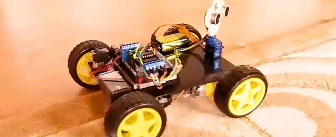
In this tutorial, we’ll build a 4-wheel drive (4WD) obstacle-avoiding robot using an Arduino, Adafruit-style Motor Shield, ultrasonic sensor, and servo motor. This robot uses the HC-SR04 ultrasonic sensor to detect obstacles in front of it. The sensor is mounted on a servo motor, allowing it to scan left and right to find the best path to move forward.
This is one of the most fun beginner robotics projects because it combines multiple core Arduino skills — motor control, sensor reading, and servo scanning — into one interactive build.
Components Required
- Arduino Uno board
- Motor Shield (Adafruit-compatible, DK Electronics clone shown)
- 4 × DC Motors (for 4WD chassis)
- 4 × Wheels
- Ultrasonic Sensor (HC-SR04)
- Servo Motor (SG90 or equivalent)
- Chassis plate
- Ultrasonic sensor holder (servo mount)
- 2 × 9V batteries (one for Arduino, one for motors)
- 2 × battery buckles
- Jumper wires
- Push button switch (for power on/off)
- Glue gun or double-sided tape
Hardware Overview
The Motor Shield used in this project can control up to 4 DC motors or 2 stepper motors and 2 servos. It is based on the L293D H-Bridge motor driver ICs, which can handle 4.5V to 25V for motor operation.
There are two options for power input:
- Through the Arduino DC jack (powers both Arduino and motors).
- Through the EXT_PWR terminal on the shield (recommended for separate motor power).
When using two separate power sources, make sure to remove the PWR jumper on the shield.
Step-by-Step Circuit Connections
1. DC Motor Connections
- Connect the left-side motors to M1 and M2 on the shield.
- If they rotate in reverse, swap the polarity of the wires.
- Connect the right-side motors to M3 and M4.
2. Servo Motor Connection
- Connect the servo motor to the Servo 1 (Digital 10) pin on the shield.
- The servo’s brown wire → GND
- The servo’s red wire → +5V
- The servo’s orange wire → Signal (D10)
3. Ultrasonic Sensor (HC-SR04)
| Sensor Pin | Arduino Connection |
|---|---|
| VCC | +5V |
| GND | GND |
| Trig | A0 |
| Echo | A1 |
The ultrasonic sensor is mounted on the servo so it can rotate and scan the area.
4. Battery and Power Switch
- Connect the (+) from the battery to one leg of the push button.
- Connect the other leg of the button to the EXT_PWR (+) terminal on the motor shield.
- Connect battery (–) to the GND terminal on the motor shield.
5. Separate Power Supply (Recommended)
- Power Arduino via its DC jack.
- Power motors through EXT_PWR terminal (4.5–12V depending on motor specs).
- Remove the yellow jumper labeled PWR when using separate supplies.
Installing Required Libraries
Before uploading the code, install the following libraries:
- Adafruit Motor Shield Library (AFMotor)
- Download: Adafruit Motor Shield Library
- Extract the ZIP file.
- Place the folder into your
Documents/Arduino/librariesdirectory.
- NewPing Library (for HC-SR04 ultrasonic sensor)
- Download: NewPing Library
- Extract and move it to your Arduino libraries folder.
- Servo Library
- Pre-installed in the Arduino IDE.
Restart the Arduino IDE after installation.
Arduino Code
#include <AFMotor.h>    // Adafruit Motor Shield library
#include <Servo.h>      // Servo control library
#include <NewPing.h>    // Ultrasonic sensor library

// Ultrasonic sensor pins
#define TRIG_PIN A0
#define ECHO_PIN A1
#define MAX_DISTANCE 300

// Motor speed and distance settings
#define MAX_SPEED 160
#define MAX_SPEED_OFFSET 40
#define COLL_DIST 30
#define TURN_DIST (COLL_DIST + 20)

NewPing sonar(TRIG_PIN, ECHO_PIN, MAX_DISTANCE);

// Define motors connected to the shield
AF_DCMotor leftMotor1(1, MOTOR12_1KHZ);
AF_DCMotor leftMotor2(2, MOTOR12_1KHZ);
AF_DCMotor rightMotor1(3, MOTOR34_1KHZ);
AF_DCMotor rightMotor2(4, MOTOR34_1KHZ);

Servo myservo;

int leftDistance, rightDistance;
int curDist = 0;
int speedSet = 0;

//--------------------------------------------- SETUP ------------------------------------------------
void setup() {
  myservo.attach(10);  // Servo connected to pin 10
  myservo.write(90);   // Center position (forward)
  delay(1000);
  Serial.begin(9600);
}
//----------------------------------------------------------------------------------------------------

//--------------------------------------------- LOOP --------------------------------------------------
void loop() {
  myservo.write(90);
  delay(90);
  curDist = readPing();
  Serial.print("Distance: ");
  Serial.print(curDist);
  Serial.println(" cm");

  if (curDist < COLL_DIST) {
    changePath();
  } else {
    moveForward();
  }
  delay(200);
}
//----------------------------------------------------------------------------------------------------

//-------------------------------------- DIRECTION CONTROL FUNCTIONS ---------------------------------
void changePath() {
  moveStop();
  myservo.write(30);    // Check right
  delay(400);
  rightDistance = readPing();

  myservo.write(150);   // Check left
  delay(400);
  leftDistance = readPing();

  myservo.write(90);    // Return to center
  delay(100);

  if (leftDistance > rightDistance) turnLeft();
  else if (rightDistance > leftDistance) turnRight();
  else turnAround();
}
//----------------------------------------------------------------------------------------------------
int readPing() {
  delay(50);
  unsigned int uS = sonar.ping();
  return uS / US_ROUNDTRIP_CM;
}
//----------------------------------------------------------------------------------------------------
void moveStop() {
  leftMotor1.run(RELEASE);
  leftMotor2.run(RELEASE);
  rightMotor1.run(RELEASE);
  rightMotor2.run(RELEASE);
}
//----------------------------------------------------------------------------------------------------
void moveForward() {
  leftMotor1.run(FORWARD);
  leftMotor2.run(FORWARD);
  rightMotor1.run(FORWARD);
  rightMotor2.run(FORWARD);

  for (speedSet = 0; speedSet < MAX_SPEED; speedSet += 2) {
    leftMotor1.setSpeed(speedSet);
    leftMotor2.setSpeed(speedSet);
    rightMotor1.setSpeed(speedSet);
    rightMotor2.setSpeed(speedSet);
    delay(5);
  }
}
//----------------------------------------------------------------------------------------------------
void moveBackward() {
  leftMotor1.run(BACKWARD);
  leftMotor2.run(BACKWARD);
  rightMotor1.run(BACKWARD);
  rightMotor2.run(BACKWARD);

  for (speedSet = 0; speedSet < MAX_SPEED; speedSet += 2) {
    leftMotor1.setSpeed(speedSet);
    leftMotor2.setSpeed(speedSet);
    rightMotor1.setSpeed(speedSet);
    rightMotor2.setSpeed(speedSet);
    delay(5);
  }
}
//----------------------------------------------------------------------------------------------------
void turnRight() {
  leftMotor1.run(FORWARD);
  leftMotor2.run(FORWARD);
  rightMotor1.run(BACKWARD);
  rightMotor2.run(BACKWARD);
  delay(800);
  moveStop();
}
//----------------------------------------------------------------------------------------------------
void turnLeft() {
  leftMotor1.run(BACKWARD);
  leftMotor2.run(BACKWARD);
  rightMotor1.run(FORWARD);
  rightMotor2.run(FORWARD);
  delay(800);
  moveStop();
}
//----------------------------------------------------------------------------------------------------
void turnAround() {
  turnRight();
  delay(1200);
}
//----------------------------------------------------------------------------------------------------
Code Explanation
- Servo scanning: The servo moves left and right to measure distances on both sides.
- NewPing library: Ensures accurate ultrasonic distance readings.
- Motor control: Four DC motors are independently controlled using the AFMotor library.
- Decision logic:
- If the object is closer than 30 cm, the robot stops and scans.
- Turns in the direction with more space.
- If both sides are blocked, it performs a 180° turn.
Testing the Robot
- Upload the code and power on your robot.
- Place obstacles around it.
- The servo-mounted ultrasonic sensor should sweep left and right.
- When it detects an object within ~30 cm, the robot will stop, scan, and decide to turn.
Tips and Improvements
- Adjust
COLL_DISTandMAX_SPEEDfor your environment. - For smoother turns, tweak
delay()values inturnLeft()andturnRight(). - You can power motors with a Li-ion battery pack (7.4V or 12V) for better performance.
- Consider adding infrared sensors for edge detection on tables or uneven surfaces.
Conclusion
You’ve just built a 4WD Arduino obstacle-avoiding robot that uses ultrasonic sensing and servo scanning to navigate autonomously. This project introduces key robotics concepts — sensor integration, motion control, and decision-making — that form the basis for more advanced autonomous systems.
Bir yanıt yazın