In this tutorial, you’ll learn how to control multiple servo motors simultaneously using an Arduino Uno R3. This setup is ideal for building projects such as robotic arms, animatronic systems, or mechanical controllers.
We’ll use four servo motors connected to Arduino PWM pins and control their motion through a simple sweep program.
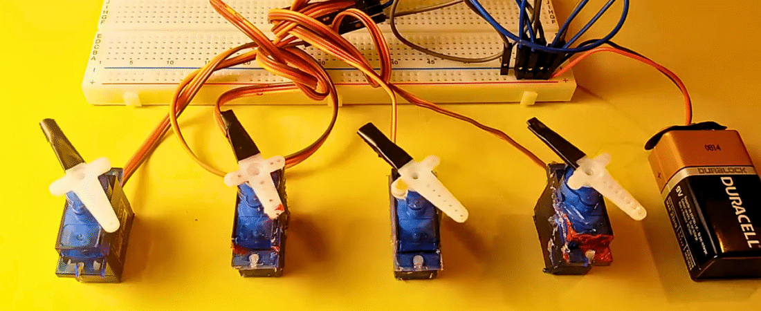
Components Required
- Arduino Uno R3
- 4 × SG90 Micro Servo Motors
- Breadboard
- Jumper wires (male-to-male)
- 9V Battery (or external 5–6V power supply for servos)
Understanding Servo Motors
Servo motors (like the SG90) are controlled by PWM (Pulse Width Modulation) signals. The servo rotates between 0° to 180°, depending on the width of the signal pulse.
- Orange wire → Signal (PWM input)
- Red wire → +5V (Power)
- Brown wire → GND
Each servo draws a significant amount of current (around 500 mA at stall), so it’s important to use an external power supply instead of powering all servos directly from the Arduino.
Circuit Connections
Power and Ground Setup
- Connect the battery (+) to the breadboard VCC line.
- Connect the battery (–) to the breadboard GND line.
- Connect Arduino GND to the breadboard GND line (common ground).
Servo Motor Connections
| Servo | Signal Pin | Power | Ground |
|---|---|---|---|
| Servo1 | Digital PWM 3 | Breadboard VCC | Breadboard GND |
| Servo2 | Digital PWM 5 | Breadboard VCC | Breadboard GND |
| Servo3 | Digital PWM 6 | Breadboard VCC | Breadboard GND |
| Servo4 | Digital PWM 9 | Breadboard VCC | Breadboard GND |
This setup ensures all servos share the same power source and control reference.
⚠️ Important Power Note
If you use multiple servos, do not power them from the Arduino’s 5V pin. Instead, use an external 5V–6V regulated power supply (e.g., 4xAA batteries or a DC adapter).
Always connect all grounds together (Arduino GND ↔ Servo GND ↔ Battery GND).
Arduino Code
#include <Servo.h>

// Create servo objects
Servo servo1;
Servo servo2;
Servo servo3;
Servo servo4;

// Servo position in degrees
int servoPos = 0;

void setup() {
  // Define servo signal pins (PWM 3, 5, 6, 9)
  servo1.attach(3);
  servo2.attach(5);
  servo3.attach(6);
  servo4.attach(9);
}

void loop() {
  // Sweep from 0° to 180°
  for (servoPos = 0; servoPos <= 180; servoPos++) {
    servo1.write(servoPos);
    servo2.write(servoPos);
    servo3.write(servoPos);
    servo4.write(servoPos);
    delay(20); // Small delay for smooth motion
  }

  // Sweep back from 180° to 0°
  for (servoPos = 180; servoPos >= 0; servoPos--) {
    servo1.write(servoPos);
    servo2.write(servoPos);
    servo3.write(servoPos);
    servo4.write(servoPos);
    delay(20);
  }
}
Code Explanation
- Servo Library:
TheServo.hlibrary handles PWM signal generation for controlling servo position. - Servo Object Creation:
Each servo motor gets its own instance (servo1,servo2,servo3,servo4). - Sweep Logic:
Twoforloops move the servos gradually between 0° and 180°, then back to 0°.
Thedelay(20)provides smooth, synchronized movement. - Synchronization:
All servos move together because each loop iteration writes the same position to every servo.
Testing the Project
- Upload the code to your Arduino Uno.
- Power the system with an external 5–6V battery.
- Observe all four servo motors sweeping together from 0° to 180° and back.
- Adjust
delay(20)for faster or slower motion.
Pro Tips
- If servos jitter, check your power source — low current can cause instability.
- You can control servos independently by assigning different motion sequences.
- Try using potentiometers to control individual servo angles in real time. (Next tutorial!)
- For more than 8 servos, consider a PCA9685 16-channel servo driver.
Conclusion
You’ve learned how to control multiple servo motors using an Arduino Uno R3.
This simple setup forms the basis for robotic arm control, biped movement, or interactive kinetic art projects.
In the next tutorial, we’ll build on this concept — using potentiometers to control multiple servos for precise manual control.
Bir yanıt yazın