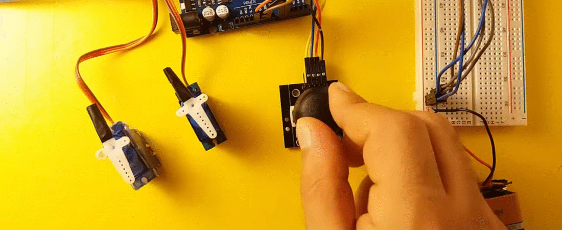
In this tutorial, you will learn how to control two servo motors using a joystick module and an Arduino Uno R3. This project demonstrates how to translate joystick movement into precise servo positioning — perfect for building robotic arms, camera gimbals, or pan-and-tilt systems.
Components Required
- Arduino Uno R3
- 2 × SG90 Micro Servo Motors
- 1 × Joystick Module (XY + SW)
- Breadboard
- Jumper Wires
- 9V Battery (or external 5–6V power source for servos)
Understanding the Joystick Module
The joystick module consists of two potentiometers (for X and Y axes) and one momentary push button (SW).
Each potentiometer outputs an analog voltage between 0 and 5V, which Arduino reads as a value between 0 and 1023.
| Pin | Function | Description |
|---|---|---|
| VCC | +5V | Power supply |
| GND | Ground | Common ground |
| VRx | Analog X | Horizontal movement |
| VRy | Analog Y | Vertical movement |
| SW | Switch | Button press (not used here) |
Circuit Connections
Power Setup
- Connect battery (+) to breadboard VCC line.
- Connect battery (–) to breadboard GND line.
- Connect Arduino GND to the breadboard GND line (common ground).
Servo Motor Connections
| Servo | Signal | Power | Ground |
|---|---|---|---|
| Servo1 | Digital PWM 3 | Breadboard VCC | Breadboard GND |
| Servo2 | Digital PWM 5 | Breadboard VCC | Breadboard GND |
Note: Always use an external 5–6V regulated supply for multiple servos. Arduino’s onboard 5V pin is not designed to power several servos at once.
Joystick Connections
| Joystick Pin | Connects To | Description |
|---|---|---|
| VCC | Arduino 5V | Power supply |
| GND | Arduino GND | Common ground |
| VRx | Arduino A0 | Controls Servo1 |
| VRy | Arduino A1 | Controls Servo2 |
| SW | Not connected | (Optional for future use) |
Arduino Code
// Add the Servo library
#include <Servo.h>

// Define our servos
Servo servo1;
Servo servo2;

// Define joystick analog pins
int joyX = A0;  // Joystick X-axis
int joyY = A1;  // Joystick Y-axis

// Variable to store joystick reading
int joyVal;

void setup() {
  // Attach servo control pins
  servo1.attach(3);
  servo2.attach(5);
}

void loop() {
  // Read X-axis value and map to servo range (0–180°)
  joyVal = analogRead(joyX);
  joyVal = map(joyVal, 0, 1023, 0, 180);
  servo1.write(joyVal);

  // Read Y-axis value and map to servo range (0–180°)
  joyVal = analogRead(joyY);
  joyVal = map(joyVal, 0, 1023, 0, 180);
  servo2.write(joyVal);

  delay(15); // Small delay for stable servo motion
}
Code Explanation
- Servo Library:
#include <Servo.h>allows Arduino to control servos using PWM signals automatically. - Analog Inputs:
The joystick outputs analog signals from 0–5V on pins VRx and VRy, which are read by Arduino’s A0 and A1. - Mapping Values:
map(value, 0, 1023, 0, 180)converts joystick readings into a range suitable for servo rotation (0°–180°). - Servo Movement:
As you move the joystick, the servos rotate smoothly in response, mimicking the joystick’s direction.
Testing Steps
- Upload the code to your Arduino Uno.
- Power the circuit using a 5–6V battery or DC adapter.
- Move the joystick:
- Move left/right → controls Servo 1.
- Move up/down → controls Servo 2.
- Both servos will follow the joystick movement in real-time.
⚠️ Troubleshooting Tips
- If servos twitch or move erratically, use a separate power supply for them.
- Always connect grounds together (Arduino, Joystick, Servo, Battery).
- If movement is reversed, swap the mapping range:
joyVal = map(joyVal, 0, 1023, 180, 0);If using a 9V battery, power only the servo VCC, not the Arduino directly (to avoid voltage regulator overheating).
Extensions
- Add the SW (button) pin to reset servos to the center position.
- Combine with an HC-SR04 ultrasonic sensor for obstacle-detection servo control.
- Expand to 4 servos using two joysticks for advanced robotic control.
Conclusion
You’ve successfully learned how to control multiple servos with a joystick using Arduino Uno R3.
This simple but powerful technique lays the foundation for robotic arm, camera gimbal, and RC controller projects.
Bir yanıt yazın