Wireless Gesture-Controlled Robotic Hand using NRF24L01+ and Arduino
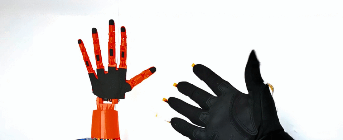
In this tutorial, we will learn how to build a wireless robotic hand controlled by a flex-sensor glove using Arduino Nano and NRF24L01+ transceivers. The project combines 3D printing, wireless communication, and servo motor control — allowing your robotic hand to mimic real hand movements in real-time.
This system is divided into two parts:
1️⃣ Transmitter (Glove) — reads finger movements via flex sensors
2️⃣ Receiver (Robotic Hand) — moves servo motors to replicate those movements
Hardware Components
| Component | Quantity | Description |
|---|---|---|
| Arduino Nano | 2 | One for glove, one for robotic hand |
| NRF24L01+ Module | 2 | Wireless communication |
| NRF24L01+ Adapter | 2 | Power stabilizer for radio module |
| MG996R Servo Motor | 5 | Controls robotic fingers |
| Flex Sensor (4.5 inch) | 5 | Detects finger bending |
| 10kΩ Resistor | 5 | Forms voltage divider with flex sensors |
| 18650 Li-ion Battery (3.7V) | 2 | Power supply for the hand |
| Battery Holder | 1 | For 18650 cells |
| 9V Battery + Clip | 1 | Power source for glove |
| Jumper Wires | Several | For connections |
| Mini Breadboard | 3 | For prototyping |
| Gloves | 1 | For mounting flex sensors |
| 3D Printed Hand and Forearm | 1 | Based on InMoov open-source design |
3D Models (Open-Source from InMoov Project):
- Official InMoov website: http://inmoov.fr/
- Direct links:
Mechanical Assembly
1️⃣ 3D Print the Hand and Forearm Parts
Download the InMoov hand STL files and print them using a standard FDM 3D printer (e.g., Ender 3 Pro).
2️⃣ Mount the Servo Motors
Install the five MG996R servos into the forearm section — one for each finger. Keep each servo initially positioned at 10° or 170° before attaching the pulleys.
3️⃣ Attach Strings (Braid Line or Fishing Wire)
Wrap the string around each servo pulley, routing it through the finger joints to create tendon-like movement. Adjust tension so fingers move smoothly when the servo rotates.
4️⃣ Add Rubber Bands or Springs
These will help fingers return to their original position when relaxed.
Transmitter Circuit (Wireless Glove)
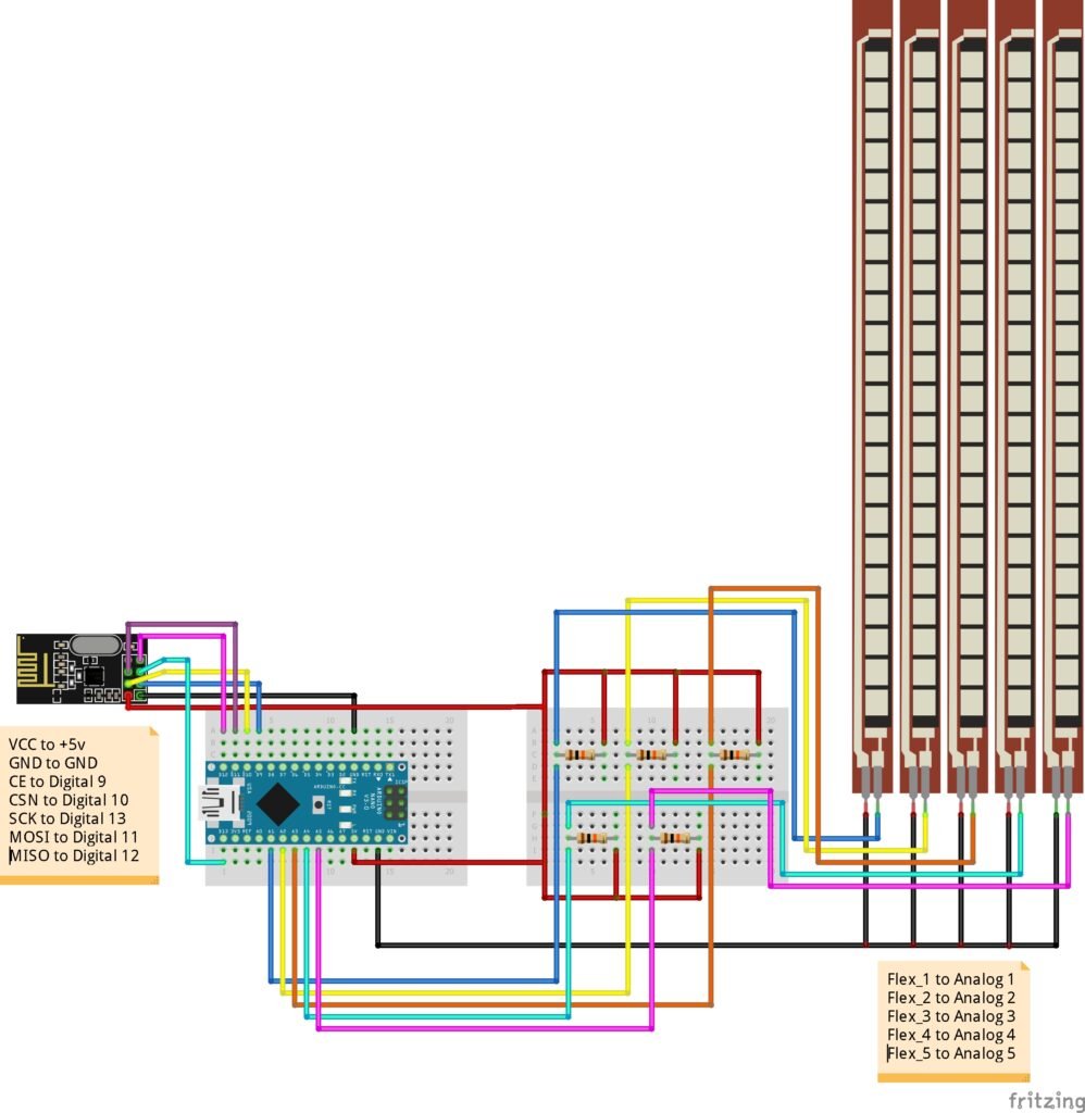
Connections of Flex Sensors
Each flex sensor acts as a variable resistor in a voltage divider circuit with a 10kΩ resistor.
| Flex Sensor | Arduino Nano Pin |
|---|---|
| Flex 1 | A1 |
| Flex 2 | A2 |
| Flex 3 | A3 |
| Flex 4 | A4 |
| Flex 5 | A5 |
Connections of NRF24L01+
Same as receiver:
- VCC → +5V
- GND → GND
- CE → D9
- CSN → D10
- SCK → D13
- MOSI → D11
- MISO → D12
🔋 Power the glove circuit using a 9V battery for portability.
Receiver Circuit (Robotic Hand)
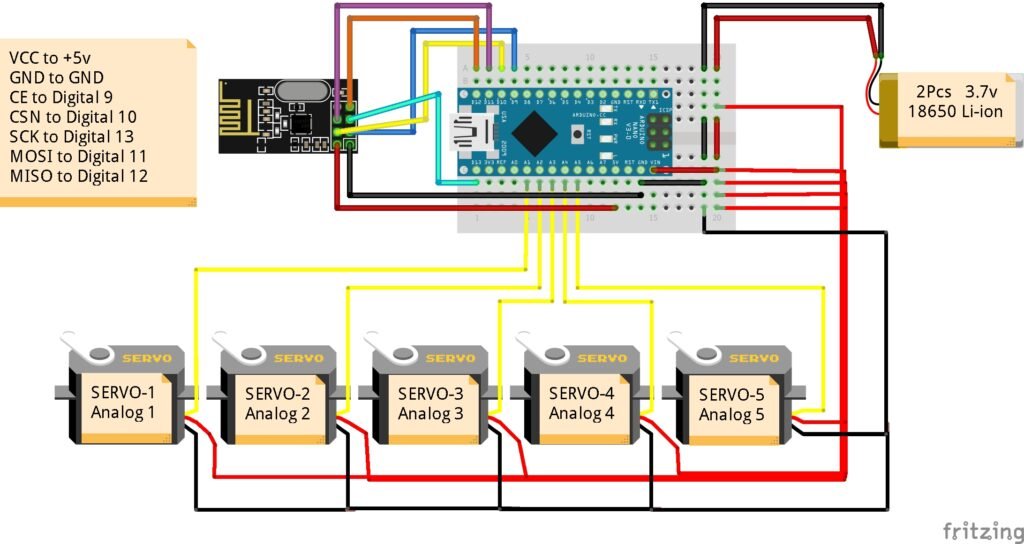
Connections of Servo Motors
| Servo | Arduino Nano Pin |
|---|---|
| Servo 1 | A1 |
| Servo 2 | A2 |
| Servo 3 | A3 |
| Servo 4 | A4 |
| Servo 5 | A5 |
Connections of NRF24L01+
| NRF24L01 Pin | Arduino Nano Pin |
|---|---|
| VCC | +5V |
| GND | GND |
| CE | D9 |
| CSN | D10 |
| SCK | D13 |
| MOSI | D11 |
| MISO | D12 |
🔋 Power Tip:
Use two 3.7V 18650 Li-ion batteries in series (~7.4V total) connected to the Arduino VIN pin or regulated 5V output for the servos. Always connect all grounds together (servo GND, Arduino GND, and power GND).
Wireless Communication Setup
The NRF24L01+ uses SPI protocol to send data packets containing five flex sensor values from the glove to the robotic hand.
- Baud rate: 2 Mbps (default)
- Frequency: 2.4 GHz
- Address:
0xE8E8F0F0E1LL
This allows low-latency gesture control without noticeable delay.
💾 Arduino Code
Before uploading the code, make sure you have installed:
📦 RF24 Library → Download from GitHub
Transmitter Code (Glove)
#include <SPI.h>
#include "RF24.h"

int msg[5];

// Flex sensor pins
int flex_5 = A5;
int flex_4 = A4;
int flex_3 = A3;
int flex_2 = A2;
int flex_1 = A1;

// Flex sensor values
int flex_5_val, flex_4_val, flex_3_val, flex_2_val, flex_1_val;

RF24 radio(9,10);
const uint64_t pipe = 0xE8E8F0F0E1LL;

void setup() {
  Serial.begin(9600);
  radio.begin();
  radio.openWritingPipe(pipe);
}

void loop() {
  flex_5_val = analogRead(flex_5);
  flex_5_val = map(flex_5_val, 630, 730, 80, 20);

  flex_4_val = analogRead(flex_4);
  flex_4_val = map(flex_4_val, 520, 710, 70, 175);

  flex_3_val = analogRead(flex_3);
  flex_3_val = map(flex_3_val, 510, 680, 140, 10);

  flex_2_val = analogRead(flex_2);
  flex_2_val = map(flex_2_val, 580, 715, 90, 175);

  flex_1_val = analogRead(flex_1);
  flex_1_val = map(flex_1_val, 550, 700, 90, 175);

  msg[0] = flex_5_val;
  msg[1] = flex_4_val;
  msg[2] = flex_3_val;
  msg[3] = flex_2_val;
  msg[4] = flex_1_val;

  radio.write(msg, sizeof(msg));
}
Receiver Code (Robotic Hand)
#include <Servo.h>
#include <SPI.h>
#include "RF24.h"

Servo myServo1, myServo2, myServo3, myServo4, myServo5;

RF24 radio(9,10);
const uint64_t pipe = 0xE8E8F0F0E1LL;

int msg[5];

void setup() {
  myServo1.attach(A1);
  myServo2.attach(A2);
  myServo3.attach(A3);
  myServo4.attach(A4);
  myServo5.attach(A5);

  radio.begin();
  radio.openReadingPipe(1, pipe);
  radio.startListening();
}

void loop() {
  if (radio.available()) {
    radio.read(msg, sizeof(msg));

    myServo1.write(msg[2]);
    myServo2.write(msg[4]);
    myServo3.write(msg[3]);
    myServo4.write(msg[1]);
    myServo5.write(msg[0]);
  }
}
Calibration Steps
1️⃣ Upload the transmitter code and open the Serial Monitor.
2️⃣ Note the minimum and maximum analog values from each flex sensor (when bent and straight).
3️⃣ Replace those calibration values inside the map() function.
4️⃣ For each servo, adjust the min/max angles (10°–170°) according to your mechanical range.
Example:
flex_val = map(flex_val, 600, 740, 10, 170);How It Works
1️⃣ The flex sensors act as variable resistors that change resistance when bent.
2️⃣ The Arduino reads these analog voltages and maps them to angles (10°–170°).
3️⃣ These values are wirelessly sent to the receiver using NRF24L01+.
4️⃣ The receiver Arduino translates those values into servo positions.
5️⃣ Each servo moves a finger proportionally — replicating your hand’s gesture.
Troubleshooting
✅ If servos vibrate → use a dedicated 5V 2A+ power source.
✅ If NRF24L01 communication fails → add capacitor (10µF) across VCC–GND near the module.
✅ If movement is reversed → swap min/max mapping values.
✅ If delay occurs → ensure both Arduinos use matching RF addresses.
Conclusion
You have successfully built a Wireless Gesture-Controlled Robotic Hand using Arduino and NRF24L01+. This project merges 3D printing, robotics, and wireless control into a single interactive system.
💡 Future upgrades:
- Add Bluetooth or Wi-Fi communication
- Implement machine learning gesture recognition
- Control a robotic arm or humanoid robot
Bir yanıt yazın