In this tutorial, we’ll build a 5-in-1 multifunctional Arduino robot that can switch between five autonomous modes — Follow Me, Line Following, Sumo, Drawing, and Obstacle Avoidance.
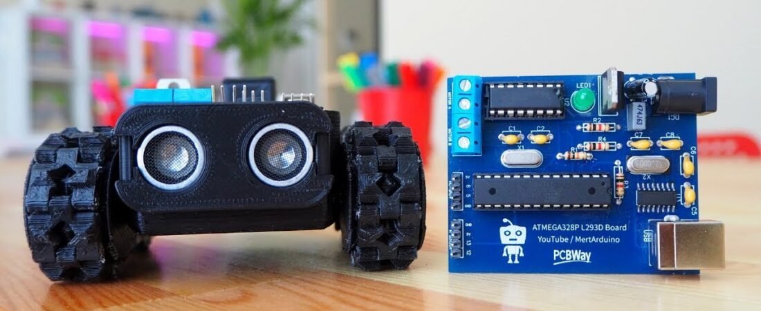
Powered by an ATmega328P-L293D driver board, this robot is compact, easy to solder, and versatile. The board integrates a motor driver (L293D) directly with the ATmega328P microcontroller, eliminating the need for separate motor shields or messy jumper connections.
With the right sensors and control logic, this project gives you a complete robotic platform that’s ideal for students, makers, and hobbyists who want to explore multiple robotics behaviors using one board.
Features of the Robot Control Board
This custom PCB combines:
- ATmega328P-PU (with bootloader) – the same chip used on Arduino Uno
- L293D Motor Driver – drives two DC motors directly from the board
- CH340G USB Interface – allows direct programming without external programmer
- Onboard Power Regulation – supports both 5V and 12V supplies
- Pin Headers for Sensors – ready-to-connect for Ultrasonic (HC-SR04) and IR sensors
It’s a self-contained robot controller, meaning you can easily program it through the Arduino IDE just like a standard Uno.
Components Required
| Component | Quantity | Notes |
|---|---|---|
| ATmega328P-PU with Bootloader | 1 | Main MCU |
| L293D Motor Driver IC | 1 | Dual DC motor control |
| HC-SR04 Ultrasonic Sensor | 1 | Distance measurement |
| IR Infrared Sensor Module | 1 | Line tracking or obstacle detection |
| 6V 200RPM Mini Metal Gear Motor | 2 | Robot movement |
| Type-B USB Socket | 1 | Programming via USB |
| L7805 Voltage Regulator | 1 | 5V power supply |
| 100µF, 470nF, 10nF, 22pF Capacitors | As listed | For decoupling and filtering |
| Resistors 10KΩ / 1KΩ / 220Ω | As listed | Biasing and LED control |
| LED (Indicator) | 1 | Power or status indication |
| 12/16 MHz Crystal | 2 | Clock for ATmega and USB |
| Power Jack Socket | 1 | External power input |
| 2-Pin Terminal Blocks | 2 | For Motor A and B outputs |
| 7.4V LiPo or 9V Battery | 1 | Power source |
| Male Pin Headers | Several | Sensor and motor connections |
PCB + 3D files available here:
👉 PCBWay Project Link
Pin Configuration Overview
🔹 Motor A Connections
| Signal | Arduino Pin |
|---|---|
| Motor A1 | D2 |
| Motor A2 | D4 |
| Motor A Enable (PWM) | D3 |
🔹 Motor B Connections
| Signal | Arduino Pin |
|---|---|
| Motor B1 | D10 |
| Motor B2 | D11 |
| Motor B Enable (PWM) | D9 |
🔹 HC-SR04 Ultrasonic Sensor
| Pin | Arduino Pin |
|---|---|
| VCC | +5V |
| GND | GND |
| Trig | D6 |
| Echo | D5 |
🔹 IR Sensor
| Pin | Arduino Pin |
|---|---|
| VCC | +5V |
| GND | GND |
| Signal | D12 or D13 |
Operating Modes
The board supports five robot modes, each programmed separately.
Each .ino file defines unique behaviors that can be uploaded via Arduino IDE.
| Mode | Description |
|---|---|
| 1. Follow Me Mode | Uses HC-SR04 to follow an object in front by measuring distance. |
| 2. Line Follower Mode | Uses IR sensors to follow a black or white line on a surface. |
| 3. Sumo Mode | Robot pushes the opponent out of a ring using IR and distance sensors. |
| 4. Obstacle Avoidance Mode | Detects obstacles and turns to avoid collisions. |
| 5. Drawing Mode | Uses a servo-controlled pen to draw shapes as it moves. |
Step-by-Step Setup Guide
Step 1: Assemble the PCB
Solder all DIP components carefully according to the silkscreen.
Start with small components (resistors, capacitors) → then IC sockets → then large components (USB, power jack, terminal blocks).
Step 2: Install the ATmega328P Bootloader
Use an existing Arduino as ISP to burn the bootloader if needed.
Once flashed, you can program it directly using the CH340G USB port.
Step 3: Connect Motors & Sensors
Refer to the diagrams above.
Ensure motor polarity and sensor power lines are correct.
Step 4: Upload Each Mode Code
Use Arduino IDE to open and upload each mode:
- Drawing_Mode.ino
- Follow_Me_Mode.ino
- Line_Follower_Mode.ino
- Obstacle_Avoiding_Mode.ino
- Sumo_Mode.ino
You can find all source codes here: 👉 PCBWay Project Link
Example: Follow Me Mode
Here’s a simplified and improved version of the Follow Me mode:
#include <NewPing.h>

#define TRIG_PIN 6
#define ECHO_PIN 5
#define MAX_DISTANCE 200

#define ENA 3
#define IN1 2
#define IN2 4
#define ENB 9
#define IN3 10
#define IN4 11

NewPing sonar(TRIG_PIN, ECHO_PIN, MAX_DISTANCE);

void setup() {
  pinMode(IN1, OUTPUT);
  pinMode(IN2, OUTPUT);
  pinMode(IN3, OUTPUT);
  pinMode(IN4, OUTPUT);
  pinMode(ENA, OUTPUT);
  pinMode(ENB, OUTPUT);
  Serial.begin(9600);
}

void loop() {
  delay(50);
  int distance = sonar.ping_cm();
  Serial.print("Distance: ");
  Serial.println(distance);

  if (distance > 0 && distance < 15) stopMotors();
  else if (distance >= 15 && distance < 30) forward();
  else if (distance >= 30) stopMotors();
  else stopMotors();
}

void forward() {
  digitalWrite(IN1, HIGH);
  digitalWrite(IN2, LOW);
  digitalWrite(IN3, HIGH);
  digitalWrite(IN4, LOW);
  analogWrite(ENA, 200);
  analogWrite(ENB, 200);
}

void stopMotors() {
  digitalWrite(IN1, LOW);
  digitalWrite(IN2, LOW);
  digitalWrite(IN3, LOW);
  digitalWrite(IN4, LOW);
}
Code Improvements Applied
✅ Replaced manual timing with NewPing library for better sensor precision.
✅ Added adjustable PWM speed control.
✅ Improved logic for smoother motion transitions.
✅ Simplified pin definitions and direction logic.
✅ Structured comments for beginners.
BOM (Bill of Materials)
The PCB BOM file includes every component with manufacturer part numbers for easy ordering — suitable for fabrication services like PCBWay.
| ID | Component | Quantity | Manufacturer |
|---|---|---|---|
| 1 | ATmega328P-PU | 1 | Microchip |
| 2 | L293D | 1 | STMicroelectronics |
| 3 | CH340G | 1 | WCH |
| 4 | L7805ABV | 1 | STMicroelectronics |
| 5 | Capacitors (10µF, 100µF, 22pF, etc.) | — | ValuePro / Dersong |
| 6 | Crystals (12MHz, 16MHz) | 2 | YXC |
| 7 | Terminal Blocks | 2 | DIBO |
| 8 | LED (XL-502SURD) | 1 | XingLight |
Conclusion
The 5-in-1 Arduino Robot is an excellent modular platform to explore robotics with ATmega328P and L293D integration.
With a single board and a few sensors, you can experiment with multiple control algorithms — from simple line following to interactive “Follow Me” behavior.
It’s a perfect learning platform for:
- Robotics students
- STEM education
- Hobby robot enthusiasts
3D robotic projects arduino projects Arduino Robot ATmega328P HC-SR04 IR Sensor L293D Line Follower pcb projects PCBWay Project Sumo Robot
Bir yanıt yazın