In this project, we will learn how to control the speed of a stepper motor using an Arduino Uno, an L293D motor driver IC, and a potentiometer. The potentiometer acts as a variable resistor that sends an analog signal to the Arduino. This signal determines the delay time between steps — in other words, the motor speed. The L293D allows the Arduino to drive the motor safely, while the potentiometer provides real-time speed control.
Parts List
- Arduino Uno board
- L293D motor driver IC
- 28BYJ-48 stepper motor (or any 4-wire stepper motor)
- 10kΩ potentiometer
- Breadboard
- Jumper wires
- External AA battery pack (for motor power)
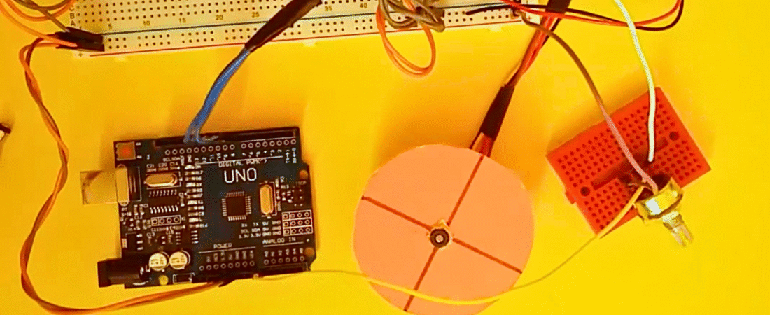
Circuit
The Arduino reads the analog value from the potentiometer through pin A0. This value is then converted to a delay time, which determines how fast the stepper motor rotates. The four control pins (8, 9, 10, 11) send a sequence of HIGH and LOW signals to the L293D, which drives the motor coils in proper order. The external battery pack supplies enough current for the motor, while the Arduino handles only the logic control.
Arduino Code
// Stepper Motor Speed Control with L293D and Potentiometer

int read_potentiometer = A0;   // Input pin for potentiometer
int LED_pin = 13;              // LED pin for indication

// Stepper motor control pins
int step_pin_1 = 8;
int step_pin_2 = 9;
int step_pin_3 = 10;
int step_pin_4 = 11;

float delay_time;
int value_potentiometer = 0;

void setup() {
  Serial.begin(9600);  // Initialize Serial Monitor
  pinMode(LED_pin, OUTPUT);
  pinMode(step_pin_1, OUTPUT);
  pinMode(step_pin_2, OUTPUT);
  pinMode(step_pin_3, OUTPUT);
  pinMode(step_pin_4, OUTPUT);
}

void loop() {
  // Read analog value from potentiometer (0–1023)
  value_potentiometer = analogRead(read_potentiometer);

  // Map potentiometer value to a usable delay range
  if (value_potentiometer > 0) {
    delay_time = 210 - (value_potentiometer / 5);  // Higher value = faster motor
  } else {
    delay_time = 0;  // Minimum speed when potentiometer is 0
  }

  Serial.println(value_potentiometer);  // Display value for debugging

  // Step sequence to rotate the motor
  digitalWrite(LED_pin, HIGH);
  digitalWrite(step_pin_1, HIGH); digitalWrite(step_pin_2, HIGH); digitalWrite(step_pin_3, LOW); digitalWrite(step_pin_4, LOW);
  delay(delay_time);

  digitalWrite(LED_pin, LOW);
  digitalWrite(step_pin_1, LOW); digitalWrite(step_pin_2, HIGH); digitalWrite(step_pin_3, HIGH); digitalWrite(step_pin_4, LOW);
  delay(delay_time);

  digitalWrite(LED_pin, HIGH);
  digitalWrite(step_pin_1, LOW); digitalWrite(step_pin_2, LOW); digitalWrite(step_pin_3, HIGH); digitalWrite(step_pin_4, HIGH);
  delay(delay_time);

  digitalWrite(LED_pin, LOW);
  digitalWrite(step_pin_1, HIGH); digitalWrite(step_pin_2, LOW); digitalWrite(step_pin_3, LOW); digitalWrite(step_pin_4, HIGH);
  delay(delay_time);
}
How It Works
- The potentiometer provides a variable voltage between 0V and 5V to the Arduino’s analog input (A0).
- The Arduino converts this voltage into a numeric value between 0 and 1023.
- This value is used to adjust the delay between motor steps — smaller delay means faster rotation.
- The L293D receives the step sequence from the Arduino and powers the motor coils accordingly.
- The LED connected to pin 13 blinks with each step, providing a visual indicator of motor activity.
This project is perfect for understanding both stepper motor control and analog input handling in Arduino. It’s a great example of combining digital logic and analog control for precise motor speed management.
Bir yanıt yazın