In this tutorial, we will learn how to control two DC motors using the L293D Dual H-Bridge Motor Driver and an Arduino Uno. The L293D IC allows you to drive two motors independently in both forward and reverse directions — ideal for small robot car projects or any application requiring precise motor control.
Hardware Required
- Arduino Uno board
- L293D Dual H-Bridge Motor Driver IC
- 2 DC Motors
- Breadboard
- Jumper wires
- External battery pack (for motor power, e.g., 4.5V–9V)
About the L293D Motor Driver
The L293D is a dual-channel H-bridge motor driver IC that can control up to two DC motors or one stepper motor. It can deliver up to 600 mA per channel (maximum 1.2 A peak).
Each side of the chip controls one motor:
- Left side pins → Motor A
- Right side pins → Motor B
The IC has two separate power pins:
- Pin 8 (Vmotor): Motor power supply (up to 36V)
- Pin 16 (Vcc): Logic power supply (typically 5V)
Both grounds (Arduino and battery) must be connected together for proper operation.
Circuit
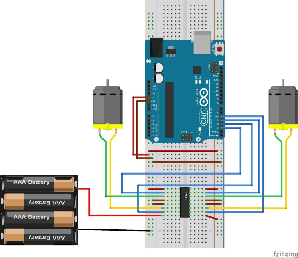
- Motor Power: The motors are powered by an external battery pack connected to pin 8 (Vmotor) on the L293D. This ensures the Arduino does not have to supply motor current directly.
- Logic Power: The 5V pin of the Arduino powers the L293D logic via pin 16 (Vcc).
- Control Pins:
- Arduino pins 2 and 3 control the left motor’s direction (forward/reverse).
- Arduino pins 4 and 5 control the right motor’s direction.
- Outputs: The outputs from the L293D (pins 3, 6, 11, and 14) connect directly to the two motors.
- Common Ground: The battery pack’s ground and the Arduino’s ground are connected together to complete the circuit.
This configuration allows full forward and backward control for both DC motors.
Code
// Define motor control pins
const int leftForward = 2;
const int leftBackward = 3;
const int rightForward = 4;
const int rightBackward = 5;

void setup() {
  // Set all motor pins as outputs
  pinMode(leftForward, OUTPUT);
  pinMode(leftBackward, OUTPUT);
  pinMode(rightForward, OUTPUT);
  pinMode(rightBackward, OUTPUT);
}

void loop() {
  // Move both motors forward
  digitalWrite(leftForward, HIGH);
  digitalWrite(leftBackward, LOW);
  digitalWrite(rightForward, HIGH);
  digitalWrite(rightBackward, LOW);

  delay(2000); // Run forward for 2 seconds

  // Move both motors backward
  digitalWrite(leftForward, LOW);
  digitalWrite(leftBackward, HIGH);
  digitalWrite(rightForward, LOW);
  digitalWrite(rightBackward, HIGH);

  delay(2000); // Run backward for 2 seconds

  // Stop both motors
  digitalWrite(leftForward, LOW);
  digitalWrite(leftBackward, LOW);
  digitalWrite(rightForward, LOW);
  digitalWrite(rightBackward, LOW);

  delay(1000); // Pause before repeating
}
How It Works
- The Arduino sends HIGH or LOW signals to the L293D input pins.
- The L293D translates these signals into motor movement:
- HIGH/LOW → Motor rotates forward
- LOW/HIGH → Motor rotates backward
- LOW/LOW → Motor stops
- The external battery pack provides sufficient current for the motors, while the Arduino only controls the logic signals.
Important Notes
- Do not power motors directly from the Arduino 5V pin. Use an external power supply (batteries or adapter).
- Always connect all grounds (GNDs) together — Arduino, battery, and L293D.
- If motors draw more than 600 mA, use a stronger motor driver like L298N or a MOSFET-based H-bridge.
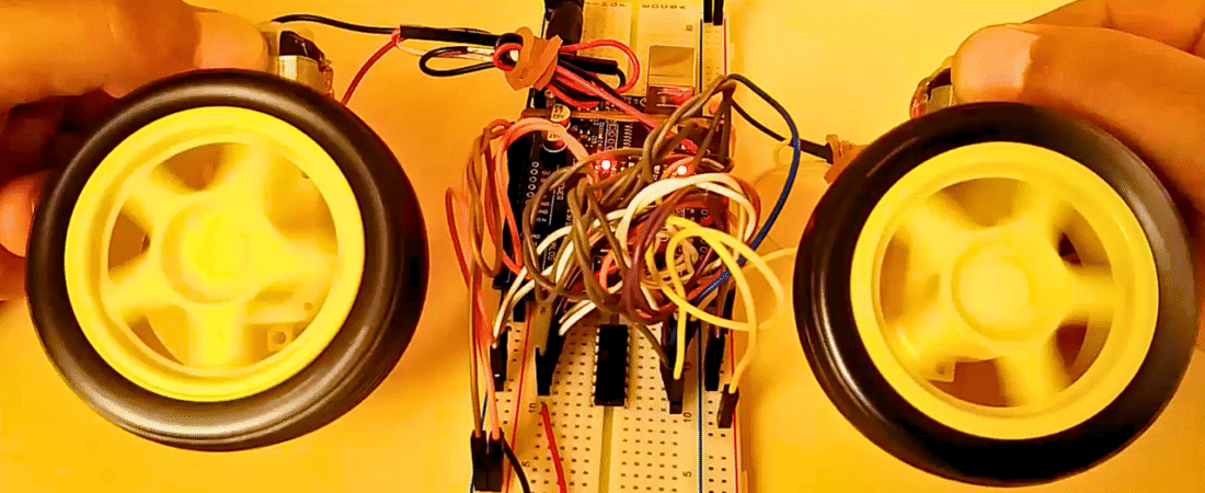
This setup is perfect for building a basic two-wheel robot car, where one motor controls each wheel. You can expand the project by adding sensors, Bluetooth, or infrared modules to automate the robot’s movements.
Bir yanıt yazın