In this tutorial, you will learn how to control an LED using a push button with the Arduino Uno. This is one of the most basic and essential beginner projects — it helps you understand how digital inputs and outputs work together in Arduino.
By the end of this guide, you’ll know how to wire a button to the Arduino, how to use resistors correctly, and how to write a simple sketch to toggle an LED when pressing the button.
Hardware Required
- Arduino Uno board
- 1 × LED (any color)
- 1 × 220Ω resistor (for LED current limiting)
- 1 × 10kΩ resistor (for button pull-down)
- 1 × Push button
- Breadboard
- Jumper wires
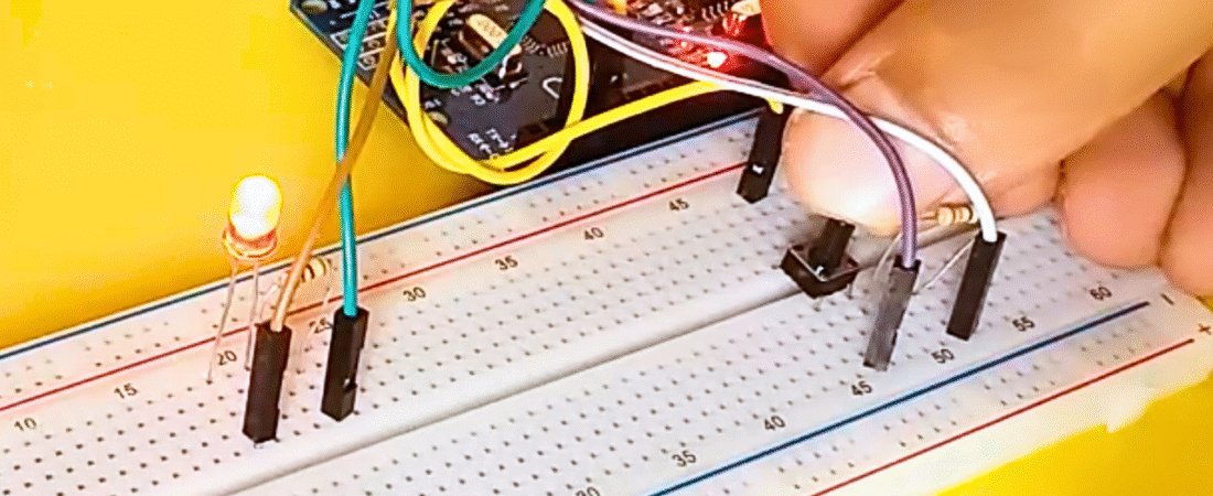
Circuit
This project connects a button to one of Arduino’s digital pins to control an LED. When you press the button, the LED turns ON. When you release it, the LED turns OFF.
1. LED Connections
- Connect the long leg (anode) of the LED to one end of the 220Ω resistor.
- Connect the other end of the resistor to digital pin 2 on the Arduino.
- Connect the short leg (cathode) of the LED directly to GND (ground).
This resistor prevents too much current from flowing through the LED, protecting it from damage.
2. Push Button Connections
- Place the push button across the breadboard’s center gap.
- Connect one side of the button to +5V on the Arduino.
- Connect the other side of the button to digital pin 4.
- Add a 10kΩ pull-down resistor between the button’s ground side and GND to keep the signal LOW when the button is not pressed.
When you press the button, the digital input pin reads HIGH (5V); when released, it reads LOW (0V).
Code
const int ledPin = 2;       // LED connected to digital pin 2
const int buttonPin = 4;    // Button connected to digital pin 4
int buttonState = 0;        // Variable for reading button status

void setup() {
  Serial.begin(9600);           // Initialize serial monitor
  pinMode(ledPin, OUTPUT);      // Set LED pin as output
  pinMode(buttonPin, INPUT);    // Set button pin as input
}

void loop() {
  buttonState = digitalRead(buttonPin);  // Read button state

  if (buttonState == HIGH) {             // If button is pressed
    digitalWrite(ledPin, HIGH);          // Turn LED ON
    Serial.println("LED ON +++++++");    // Print status
  }
  else {                                 // If button not pressed
    digitalWrite(ledPin, LOW);           // Turn LED OFF
    Serial.println("LED OFF -------");   // Print status
  }
}
How the Code Works
- The buttonPin reads either HIGH or LOW using digitalRead().
- If the button is pressed, Arduino sets the ledPin HIGH — turning the LED ON.
- If the button is not pressed, ledPin is set LOW — turning the LED OFF.
- The Serial Monitor prints the LED status, allowing you to see button activity in real time.
Common Issues and Fixes
- LED always ON or flickering: This usually happens if the button input pin is left “floating” (not connected to a stable voltage). Make sure to use a 10kΩ pull-down resistor or configure the internal pull-up resistor with pinMode(buttonPin, INPUT_PULLUP) and reverse your logic in the code.
- LED too dim or not lighting up: Check that your LED’s polarity is correct (long leg to resistor/pin, short leg to GND).
- No response in Serial Monitor: Verify that your baud rate (9600) matches both in code and Serial Monitor settings.
Upgrade Ideas
- Modify the code to toggle the LED with each button press (turn ON once, press again to turn OFF).
- Use multiple buttons to control multiple LEDs.
- Replace the LED with a relay to control higher-power devices.
Conclusion
This simple project demonstrates the basics of digital input/output control with Arduino. By pressing a button, you send a digital HIGH signal that turns ON an LED — a fundamental concept used in nearly every Arduino project, from robots to home automation systems.
With just a few components, you’ve built the foundation for understanding how sensors, buttons, and actuators interact in microcontroller projects.
Bir yanıt yazın