In this tutorial, we’ll create a light-sensitive alarm system using an LDR (photoresistor), a buzzer, and an LED with an Arduino Uno. When the light intensity increases (for example, when sunlight or a flashlight hits the LDR), the buzzer sounds and the LED flashes.
This project is a great example of how light sensors can be used for security alarms, automatic notifications, or environmental monitoring systems.
Hardware Required
- Arduino Uno board
- Buzzer module or passive buzzer
- LED
- 1 × LDR (photoresistor)
- 1 × 220Ω resistor (for LED)
- 1 × 10kΩ resistor (for LDR voltage divider)
- Breadboard
- Jumper wires
How It Works
The LDR (Light Dependent Resistor) changes its resistance depending on the amount of light it receives:
- In darkness, its resistance is high.
- Under bright light, its resistance is low.
By connecting the LDR and a 10kΩ resistor in a voltage divider configuration, Arduino can measure the light level on its analog input (A0).
When the light intensity rises above a certain threshold (e.g., 400), Arduino triggers the buzzer and LED, creating a visual and sound alert.
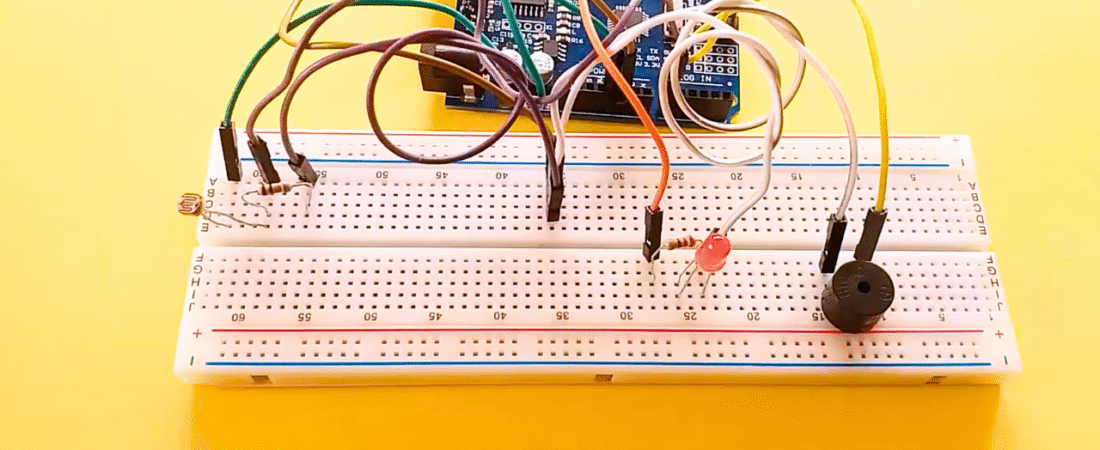
Circuit Explanation
1. LDR and Voltage Divider
- Connect one leg of the LDR to +5V on the Arduino.
- Connect the other leg of the LDR to both:
- Analog pin A0 on Arduino.
- One side of the 10kΩ resistor.
- Connect the other side of the 10kΩ resistor to GND.
This forms a voltage divider that outputs a varying voltage depending on the light level.
2. LED Connection
- Connect the long leg (anode) of the LED to one end of a 220Ω resistor.
- Connect the other end of the resistor to digital pin 13.
- Connect the short leg (cathode) of the LED to GND.
The resistor limits current and protects the LED.
3. Buzzer Connection
- Connect the positive leg (+) of the buzzer to digital pin 12.
- Connect the negative leg (-) of the buzzer to GND.
Arduino Code
const int ledPin = 13;     // LED connected to digital pin 13
const int buzzerPin = 12;  // Buzzer connected to digital pin 12
const int ldrPin = A0;     // LDR connected to analog pin A0

void setup() {
  Serial.begin(9600);        // Initialize serial monitor
  pinMode(ledPin, OUTPUT);   // Set LED as output
  pinMode(buzzerPin, OUTPUT);// Set buzzer as output
  pinMode(ldrPin, INPUT);    // Set LDR as input
}

void loop() {
  int ldrStatus = analogRead(ldrPin);  // Read LDR value
  Serial.print("LDR Value: ");
  Serial.println(ldrStatus);

  if (ldrStatus >= 400) {  // Threshold for light intensity
    tone(buzzerPin, 1000);     // Activate buzzer with 1kHz tone
    digitalWrite(ledPin, HIGH);// Turn LED ON
    delay(200);                // Wait a short time
    noTone(buzzerPin);         // Stop buzzer
    digitalWrite(ledPin, LOW); // Turn LED OFF
    delay(200);
    Serial.println("ALARM ACTIVATED: Bright light detected!");
  }
  else {
    noTone(buzzerPin);         // Keep buzzer off
    digitalWrite(ledPin, LOW); // LED off
    Serial.println("System idle: Low light detected.");
  }

  delay(100); // Small delay for stability
}
How the Code Works
- Arduino continuously reads the LDR value using analogRead(A0).
- If the light intensity (LDR reading) exceeds 400, the system activates:
- The buzzer sounds.
- The LED blinks to indicate alarm activation.
- If the light intensity is below 400 (dark environment), both LED and buzzer remain off.
- The Serial Monitor displays the real-time LDR value and system state.
You can adjust the threshold (400) depending on your room’s brightness or application needs.
Applications
- Light-activated alarm systems
- Theft detection (when a beam of light is broken or triggered)
- Smart garden or solar panel monitoring
- Automatic sunlight alert for indoor plants or photography setups
Troubleshooting Tips
- If the buzzer and LED remain ON, lower the threshold value (try 250–300).
- If nothing happens, check the LDR orientation and ensure the voltage divider is wired correctly.
- Use Serial.println(ldrStatus) to monitor live readings and calibrate your setup.
- Make sure the buzzer you use supports digital output control (active or passive).
Conclusion
This Arduino LDR Alarm Project demonstrates how light sensors can be used to detect environmental changes and trigger alerts using simple components.
By combining an LDR, buzzer, and LED, you’ve created a basic light-activated security or alert system — a perfect foundation for advanced IoT or automation applications.
Bir yanıt yazın