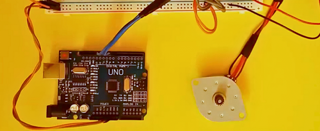
In this project, we will learn how to control a 28BYJ-48 stepper motor using an Arduino Uno and the L293D motor driver IC. The L293D allows the Arduino to control the motor direction and step sequence safely without overloading its pins. The project demonstrates the basic concept of rotating a stepper motor in one direction with precise control using digital outputs.
Parts List
- Arduino Uno board
- L293D motor driver IC
- 28BYJ-48 stepper motor (or any 4-wire stepper motor)
- Breadboard
- Jumper wires
- External battery pack (for motor power)
Circuit Explanation
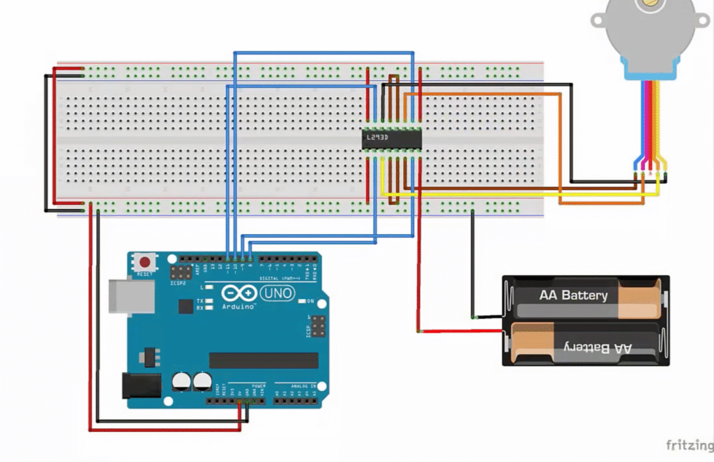
In this circuit, the Arduino Uno controls the stepper motor through the L293D motor driver IC. The L293D acts as a bridge between the low-power Arduino pins and the higher current required by the motor.
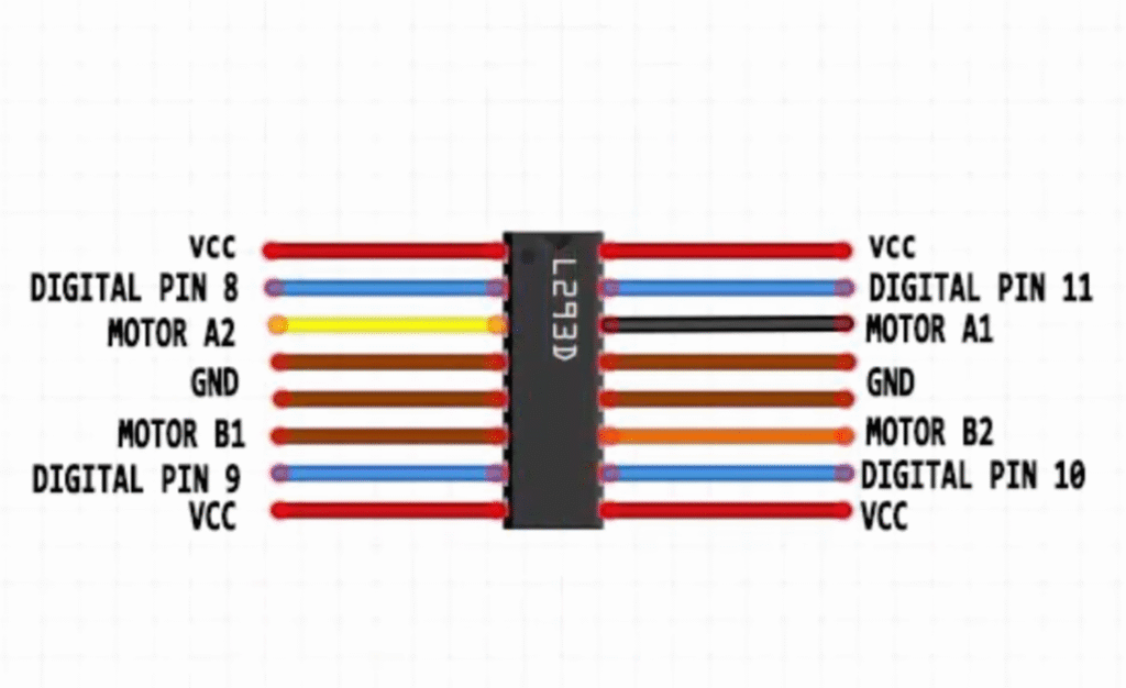
- The four Arduino digital pins (8, 9, 10, 11) are connected to the L293D inputs, which control the direction and sequence of the motor coils.
- The stepper motor’s four wires are connected to the L293D output pins (Motor A1, A2, B1, B2).
- A separate battery pack provides power to the motor through the L293D’s motor supply pin (Vcc2), while the Arduino provides logic power (Vcc1).
- The ground (GND) of the battery pack and the Arduino are connected together to share a common reference point.
This setup allows the Arduino to rotate the stepper motor precisely by energizing the coils in sequence without overloading its I/O pins.
Arduino Code
// Stepper Motor Control using L293D and Arduino
// This code drives a 4-wire stepper motor in one direction

int motorPin1 = 8;   // IN1 on L293D
int motorPin2 = 9;   // IN2 on L293D
int motorPin3 = 10;  // IN3 on L293D
int motorPin4 = 11;  // IN4 on L293D
int delayTime = 50;  // Delay between steps (lower = faster speed)

void setup() {
  // Set motor control pins as outputs
  pinMode(motorPin1, OUTPUT);
  pinMode(motorPin2, OUTPUT);
  pinMode(motorPin3, OUTPUT);
  pinMode(motorPin4, OUTPUT);
}

void loop() {
  // Step sequence to rotate the motor
  digitalWrite(motorPin4, HIGH);
  digitalWrite(motorPin3, LOW);
  digitalWrite(motorPin2, LOW);
  digitalWrite(motorPin1, LOW);
  delay(delayTime);

  digitalWrite(motorPin4, LOW);
  digitalWrite(motorPin3, HIGH);
  digitalWrite(motorPin2, LOW);
  digitalWrite(motorPin1, LOW);
  delay(delayTime);

  digitalWrite(motorPin4, LOW);
  digitalWrite(motorPin3, LOW);
  digitalWrite(motorPin2, HIGH);
  digitalWrite(motorPin1, LOW);
  delay(delayTime);

  digitalWrite(motorPin4, LOW);
  digitalWrite(motorPin3, LOW);
  digitalWrite(motorPin2, LOW);
  digitalWrite(motorPin1, HIGH);
  delay(delayTime);
}
How It Works
- The Arduino sends HIGH and LOW signals to the four L293D input pins (IN1–IN4).
- The L293D amplifies these signals to drive the motor coils in sequence.
- The delay between steps determines the motor speed.
- By changing the order of the sequence, you can reverse the motor direction.
This setup is ideal for beginners learning stepper motor basics, and can be expanded for more advanced motion control applications.
Bir yanıt yazın