In this simple Arduino project, we’ll build a light-sensitive LED control system using an LDR (Light Dependent Resistor). The LED will automatically turn ON in the dark and turn OFF in bright light.
This project demonstrates how to use analog sensor data with Arduino — a great starting point for learning automation and sensor-based control.
Components Required
- Arduino Uno
- LDR (Photoresistor)
- LED
- 220 Ω resistor (for LED)
- 10 kΩ resistor (for LDR voltage divider)
- Breadboard
- Jumper wires
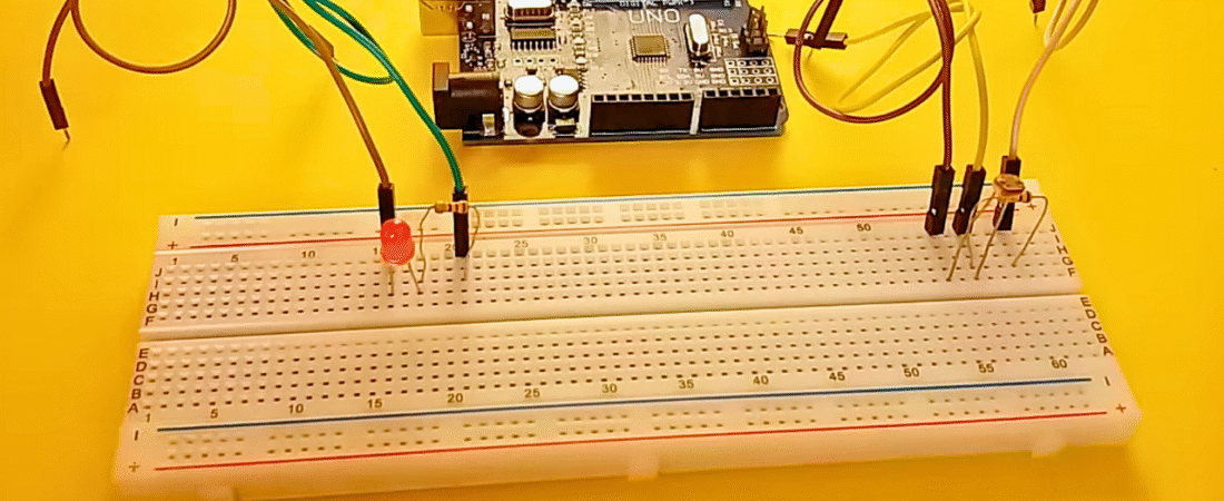
Circuit Connections
- LED Connection
- The long leg (anode) of the LED → 220 Ω resistor → Arduino digital pin 13
- The short leg (cathode) of the LED → Arduino GND
- LDR Connection
- One leg of the LDR → Arduino 5 V
- The other leg of the LDR → Arduino A0
- From the same column as A0, connect a 10 kΩ resistor → Arduino GND
This forms a voltage divider circuit, allowing the Arduino to measure the light intensity as an analog voltage.
When light increases, the LDR resistance drops. When it’s dark, resistance increases — and we can detect this change.
How the Code Works
- The LDR provides an analog voltage to Arduino’s A0 pin.
- The Arduino reads this value (0–1023 range).
- If the reading is below 300, it means the room is dark → the LED turns ON.
- If it’s above 300, the LED turns OFF.
- The light levels are also printed on the Serial Monitor.
Arduino Code
// Arduino - LDR With LED
// Automatically turn LED on in dark, off in light

// Define pins
const int ledPin = 13;   // LED connected to digital pin 13
const int ldrPin = A0;   // LDR connected to analog pin A0

void setup() {
  Serial.begin(9600);           // Start serial communication
  pinMode(ledPin, OUTPUT);      // LED as output
  pinMode(ldrPin, INPUT);       // LDR as input
}

void loop() {
  int ldrStatus = analogRead(ldrPin);  // Read LDR value

  Serial.print("LDR Value: ");         // Print sensor value
  Serial.println(ldrStatus);

  if (ldrStatus <= 300) {              // Check darkness level
    digitalWrite(ledPin, HIGH);        // Turn LED on
    Serial.println("LDR is DARK, LED is ON");
  } else {
    digitalWrite(ledPin, LOW);         // Turn LED off
    Serial.println("LDR is BRIGHT, LED is OFF");
  }

  delay(200); // Small delay for stable readings
}
Explanation Step by Step
- Setup Phase
- Serial Monitor is started at 9600 baud.
- The LED pin is set as
OUTPUT. - The LDR pin is set as
INPUT.
- Loop Phase
- The LDR value is read continuously.
- A threshold (300) decides whether the environment is bright or dark.
- The LED turns ON or OFF accordingly.
- The status is displayed in the Serial Monitor.
Testing the Project
- Upload the code to Arduino.
- Open Tools → Serial Monitor (9600 baud).
- Cover the LDR with your hand — you’ll see:
LDR is DARK, LED is ONThe LED lights up.
Expose it to light — you’ll see:
LDR is BRIGHT, LED is OFFThe LED turns off.
Project Ideas and Improvements
- Use PWM (analogWrite) to make LED brightness change smoothly with light level.
- Replace LED with a relay module to control lamps or fans.
- Use digital light sensors like BH1750 or TSL2561 for more precision.
- Combine with an RTC module to create a smart night-lamp system.
Conclusion
This project demonstrates how easily Arduino can read analog sensor data and control outputs.
By using an LDR, you’ve created a basic but practical automatic lighting system — the same principle used in smart street lights and home automation devices.
Bir yanıt yazın