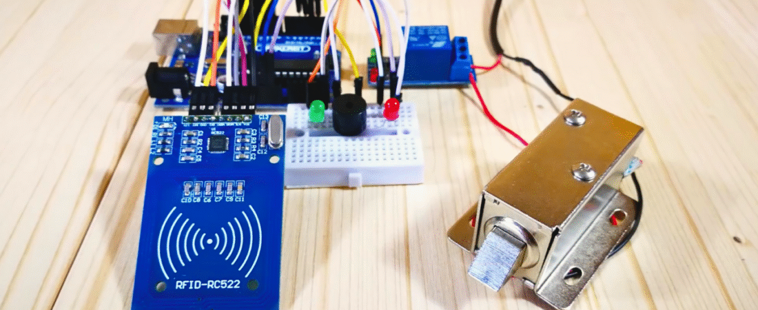
In this project, we’ll build a Solenoid Door Lock Control System using Arduino and an RFID RC522 module. This system allows door access only to users with authorized RFID cards. When an authorized card is detected, the relay activates, unlocking the 12V solenoid lock for a short time.
If an unauthorized card is scanned, a red LED lights up and the buzzer sounds, denying access.
This is one of the most practical and beginner-friendly projects for home, office, or lab security automation — combining electronics, programming, and RFID technology.
Components Required
| Component | Quantity | Description |
|---|---|---|
| Arduino Uno | 1 | Main microcontroller |
| RC522 RFID Reader | 1 | Reads RFID cards or tags |
| 12V Solenoid Door Lock | 1 | Electrically controlled lock |
| Relay Module (5V) | 1 | Switches the 12V lock safely |
| 12V Power Adapter | 1 | Powers the solenoid lock |
| Breadboard | 1 | For LEDs and buzzer wiring |
| Red LED | 1 | Indicates “Access Denied” |
| Green LED | 1 | Indicates “Access Granted” |
| Active Buzzer | 1 | Provides sound alerts |
| Jumper Wires | Several | For connections |
System Overview
The RFID RC522 reads the UID (unique ID) of the card placed on it.
This ID is compared to a predefined authorized UID in the Arduino code.
- If it matches, the relay activates — unlocking the solenoid lock for 2 seconds.
- If not, a buzzer and red LED alert indicate “Access Denied.”
Circuit Connections
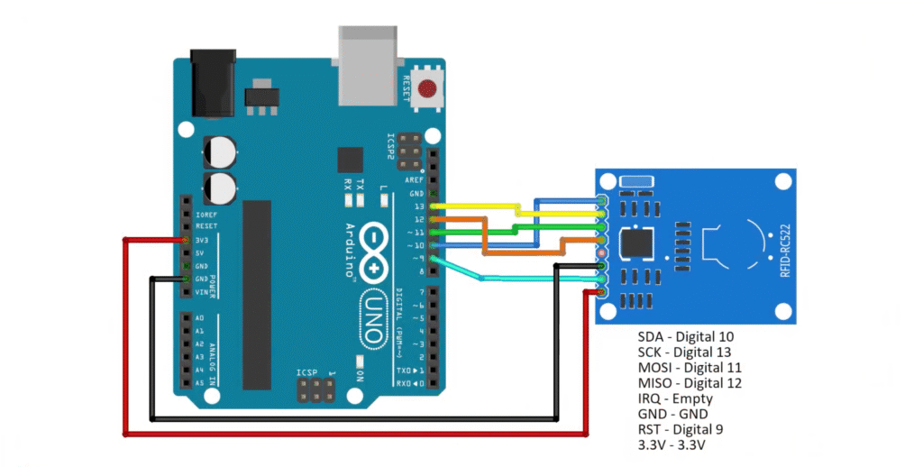
RFID RC522 → Arduino Uno
| RFID Pin | Arduino Pin |
|---|---|
| SDA | D10 |
| SCK | D13 |
| MOSI | D11 |
| MISO | D12 |
| RST | D9 |
| GND | GND |
| 3.3V | 3.3V |
⚠️ Important: The RC522 operates at 3.3V logic. Never connect it to 5V.
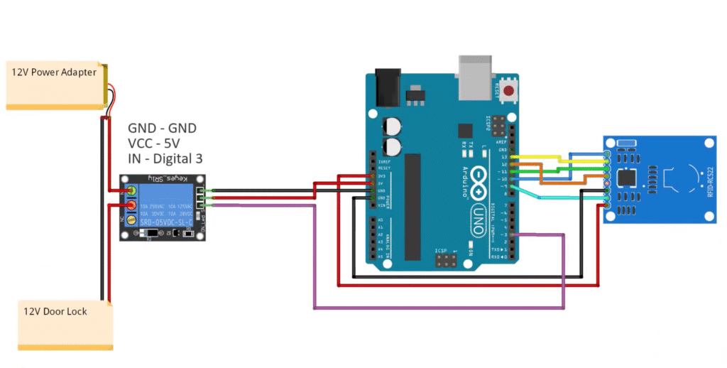
Relay Module → Arduino + Power
| Relay Pin | Connection |
|---|---|
| IN | D3 |
| VCC | 5V |
| GND | GND |
Relay Output Wiring:
- COM → 12V Adapter (+)
- NO (Normally Open) → Solenoid Lock (+)
- Solenoid Lock (−) → Adapter (−)
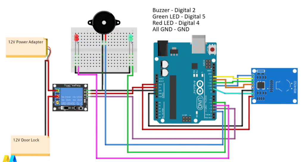
LED + Buzzer
| Component | Arduino Pin |
|---|---|
| Buzzer | D2 |
| Green LED | D5 |
| Red LED | D4 |
| All Grounds | Common GND |
⚡ Power Supply Setup
- The Arduino is powered via USB or a separate 9V adapter.
- The relay and solenoid lock use a 12V adapter.
- Always connect GND of Arduino and relay together for proper logic reference.
Required Library
Before uploading the code, install the MFRC522 RFID library by Miguel Balboa.
📦 Download: MFRC522 GitHub Repository
To install:
- Open Arduino IDE → Sketch → Include Library → Add .ZIP Library
- Select the downloaded ZIP file.
- Verify it appears under File → Examples → MFRC522.
How the Code Works
1️⃣ The Arduino initializes the SPI bus and RFID module.
2️⃣ It constantly scans for new RFID cards.
3️⃣ When a card is detected, the UID is read and displayed on the Serial Monitor.
4️⃣ The UID is compared with the predefined authorized value in the code.
5️⃣ If authorized:
- The relay activates (unlocking the door).
- The green LED lights up.
- After a delay, the system resets.
6️⃣ If unauthorized: - The red LED turns on.
- The buzzer sounds briefly.
- The system waits for another card.
Step-by-Step Procedure
Step 1 — Get Your Card UID
Upload the code below to read RFID tags:
#include <SPI.h>
#include <MFRC522.h>

#define SS_PIN 10
#define RST_PIN 9
MFRC522 mfrc522(SS_PIN, RST_PIN);

void setup() {
  Serial.begin(9600);
  SPI.begin();
  mfrc522.PCD_Init();
  Serial.println("Put your card to the reader...");
}

void loop() {
  if (!mfrc522.PICC_IsNewCardPresent()) return;
  if (!mfrc522.PICC_ReadCardSerial()) return;
  Serial.print("UID tag: ");
  for (byte i = 0; i < mfrc522.uid.size; i++) {
    Serial.print(mfrc522.uid.uidByte[i] < 0x10 ? " 0" : " ");
    Serial.print(mfrc522.uid.uidByte[i], HEX);
  }
  Serial.println();
  delay(1000);
}
Open Serial Monitor at 9600 baud.
Tap your RFID card to the reader.
Copy the UID (e.g., D5 A8 87 43).
Step 2 — Update the Access Control Code
Replace "XX XX XX XX" in the code below with your card’s UID.
#include <SPI.h>
#include <MFRC522.h>

#define SS_PIN 10
#define RST_PIN 9
#define LED_G 5        // Green LED
#define LED_R 4        // Red LED
#define RELAY 3        // Relay pin
#define BUZZER 2       // Buzzer pin
#define ACCESS_DELAY 2000
#define DENIED_DELAY 1000

MFRC522 mfrc522(SS_PIN, RST_PIN);   // Create MFRC522 instance

void setup() {
  Serial.begin(9600);
  SPI.begin();
  mfrc522.PCD_Init();

  pinMode(LED_G, OUTPUT);
  pinMode(LED_R, OUTPUT);
  pinMode(RELAY, OUTPUT);
  pinMode(BUZZER, OUTPUT);

  digitalWrite(RELAY, HIGH);  // Lock closed initially
  noTone(BUZZER);

  Serial.println("Put your card to the reader...");
  Serial.println();
}

void loop() {
  // Wait for a new card
  if (!mfrc522.PICC_IsNewCardPresent()) return;
  if (!mfrc522.PICC_ReadCardSerial()) return;

  Serial.print("UID tag :");
  String content = "";
  for (byte i = 0; i < mfrc522.uid.size; i++) {
    Serial.print(mfrc522.uid.uidByte[i] < 0x10 ? " 0" : " ");
    Serial.print(mfrc522.uid.uidByte[i], HEX);
    content.concat(String(mfrc522.uid.uidByte[i] < 0x10 ? " 0" : " "));
    content.concat(String(mfrc522.uid.uidByte[i], HEX));
  }

  content.toUpperCase();
  Serial.println();
  Serial.print("Message : ");

  // Replace this UID with your authorized card’s UID
  if (content.substring(1) == "D5 A8 87 43") {
    Serial.println("Authorized access");
    digitalWrite(RELAY, LOW);      // Unlock door
    digitalWrite(LED_G, HIGH);
    delay(ACCESS_DELAY);
    digitalWrite(RELAY, HIGH);     // Lock again
    digitalWrite(LED_G, LOW);
  } else {
    Serial.println("Access denied");
    digitalWrite(LED_R, HIGH);
    tone(BUZZER, 300);
    delay(DENIED_DELAY);
    digitalWrite(LED_R, LOW);
    noTone(BUZZER);
  }
}
Improvements Made
✅ Replaced hardcoded delays with constants for clarity.
✅ Simplified UID string handling for stability.
✅ Added serial feedback for debugging.
✅ Organized wiring comments for easier maintenance.
✅ Ensured all grounds are common — preventing relay misbehavior.
Troubleshooting Tips
- If “No card detected”, check wiring (especially MISO/MOSI/SCK pins).
- If the relay doesn’t activate, verify that VCC = 5V and IN = D3.
- Always power the solenoid from 12V, not from Arduino.
- For multiple authorized cards, duplicate the
ifcondition:
if (content.substring(1) == "D5 A8 87 43" || content.substring(1) == "05 DF FB 6C")You’ve just created a Smart RFID Door Lock System using Arduino and the RC522 module!
This system provides reliable, card-based access control that can easily be expanded for:
- Offices and labs
- Smart home door systems
- Locker or cabinet access control
3D robotic projects arduino projects Arduino Robot ATmega328P HC-SR04 IR Sensor L293D Line Follower pcb projects PCBWay Project Sumo Robot
Bir yanıt yazın